Before performing calibration, please allow your thermostat to have been powered for at least an hour in the location of intended use. It is best to perform calibration when the HVAC equipment is idle so that airflow does not alter readings. The thermostat vents internal heat from slots at the top of the thermostat so please place your measurement instrument as close to the lower left corner of the thermostat as practical to be near the internal sensor.
Press/hold SETUP button (behind the hinged door) until the whole screen lights up. Release SETUP, then press MODE enough times until ‘CALIBRATE SENSORS?’ appears on the scrolling display. Press UP to get into the calibration section then follow the displayed instructions. Press SETUP to exit once done.
The thermostat is powered directly by the HVAC unit and should be receiving 24V AC across the R and C terminals of its baseplate.
Check the circuit breaker for the unit and make sure it has not been tripped. If the air filter has been replaced recently, make certain that the furnace panels are all secure. If you cannot find anything obvious, we would suggest reaching out to a local licensed heating / air conditioning company for assistance.
There are many things that can cause the thermostat to go offline and troubleshooting can be a challenge. One thing to be aware of is that none of the Venstar connected thermostats require skyweb access to function. The thermostat (if powered) will still be controlling the space to the last mode/setpoints and running a schedule normally if it was in that mode.
We find that wifi connectivity is far less reliable when the wifi signal strength drops below 60%. Please check the signal strength by pressing ACCESSORY SETUP, then MODE, then UP until ‘SIGNAL STRENGTH’ is shown. If the indicated signal strength is below 60%, try moving the router closer to the thermostat or placing it in a more open area with fewer obstructions.
It may also be helpful to cycle power to the thermostat and your wifi router. Popping the thermostat off/on the subbase will cycle power to it.
This happens when the thermostat can not reach skyport. If you are certain that the wifi router has good internet access, please check the module firmware revision via ACCESSORY STATUS, WARMER then MODE until MODULE VERSION appears on the scrolling display. If the module firmware is below 2.16, that could cause this issue. Please use the ? Contact Us link on the lower right of your screen to let us know about this issue and we will email you with instructions.
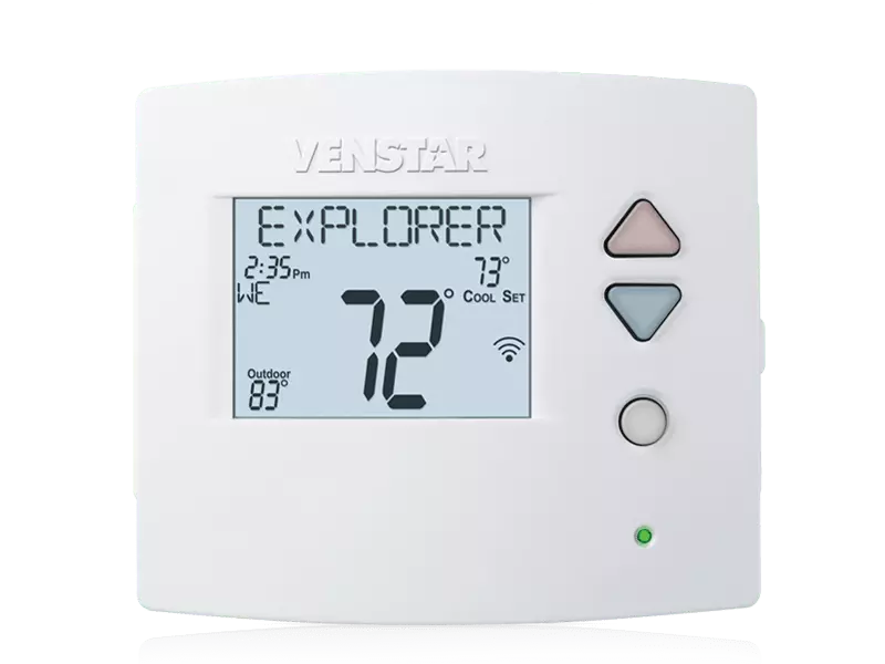
The Explorer models (T3700, T3800, T3900, T4700, T4800, T4900, T4900SCH) require use of an optional wifi module, part number ACC-VWF2, to connect to skyport over wifi. If you get this error and do have a module installed, please closely look at the module part number to make certain it is ACC-VWF2.
The longest recommended sensor cable length is 200 ft. If the cable between thermostat and remote sensor is routed near any a.c. signals (lighting, power cables, alarm signals, even the HVAC wires), noise can be induced and cause the reading to fluctuate. Please try to re-route the cable to keep it away from those a.c. signals. If the reading is still bouncing, a small component (electrolytic capacitor) can be attached to the two sensor terminals at the backplate. Use the ? Contact Us link on the lower right of your screen to let us know about this issue and we will email you with instructions.
The Explorer uses a 10K NTC type 2 curve thermistor for remote temperature sensing. Our ACC-TSEN or ACC-DSEN sensors are suitable. Note that while all models support a wired outdoor sensor, only models T3800, T3900, T4700, T4900 and T4900SCH support a remote wired sensor to be used for temperature control.
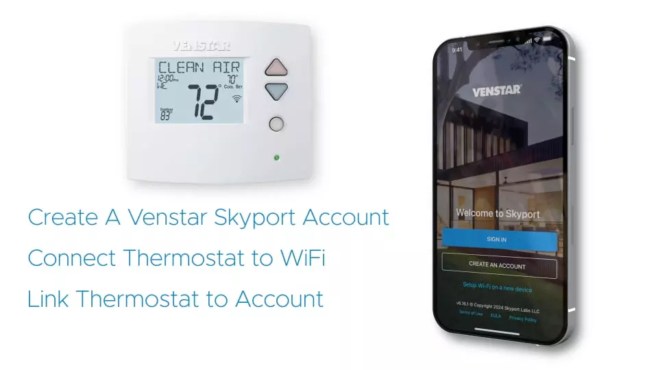
Skyport connected thermostats will constantly try to connect to the Skyport Cloud Services servers, if you successfully configured a WiFi connection and the Skyport option is enabled. An unsuccessful connection attempt will cause your thermostat to schedule a retry a few minutes later.
Please use the following check points to eliminate any network issues preventing your thermostat connecting to the Skyport Cloud Services servers.
Symptom: This is usually caused by a high temperature safety limit opening on the furnace. When the safety opens, the furnace shuts off the burners and disconnects the 24VAC to the thermostat causing the thermostat clock to stop. In order to cool down the heat exchanger, the furnace blower will remain energized for approximately 15 minutes before restoring power to the thermostat and, if there is still a call for heating, allowing the furnace to re-energize. In this situation homeowner may never notice a problem, except that the clock will be off by the number minutes power was disconnected.
Correction: Determine what is causing the high temperatures to occur - dirty filter, etc.
Symptom: Many of our thermostats have the ability to, in addition to other security features*, lock out the thermostat buttons entirely.
Correction: To lock or unlock the thermostat buttons, press and hold the MODE button. While you are holding the MODE button, press the UP and DOWN arrow buttons as well.
*NOTE: Many of our commercial thermostats have advanced security features that also disable certain button functions. If some, but not all, of your buttons are locked out, then you will need to disable the security setting. Consult the Owner’s Manual of the thermostat in order to disable the security setting of your thermostat.
Symptom: When the thermostat is placed on a wall that has no insulation, air will often blow on the thermostat sensor from behind the wall. This air will remain the same temperature even though the space temperature is being heated or cooled.
Correction: Insulate the hole behind the thermostat with insulation, spray foam, or even duct tape - whatever will stop the airflow from behind the wall.
Symptom #1: This usually occurs when a gas/electric thermostat is attempting to control a heat pump system.
Correction #1: If your thermostat is heat pump compatible, follow the instructions below to program the thermostat for heat pump operation. This will entail changing the jumper settings on the thermostat circuit board or selecting heat pump operation in the advanced setup programming.
Jumper Setting – Pull your thermostat away from the sub-base. The jumpers will be located in the upper right hand corner of the circuit board. Locate the middle jumper that can be set for GAS or HP operation. Place the jumper on the two pins closest to HP.
Advanced Setup – Press the MODE and PROGRAM or MODE and FAN buttons to enter advanced setup. Then press the MODE button repeatedly until HP appears in the middle of the screen. Press the UP button so that ON is displayed. Press PROGRAM or MODE and FAN to exit advanced setup.
Symptom #2: This may also occur when the reversing valve setting of a heat pump compatible thermostat has been programmed incorrectly.
Correction #2: Follow the instructions below to program the thermostat for the correct reversing valve setting. This will entail changing the jumper settings on the thermostat circuit board or selecting the operation in the advanced setup programming.
Jumper Setting – Pull your thermostat away from the sub-base. The jumpers will be located in the upper right hand corner of the circuit board. Locate the bottom jumper that can be set for O or B operation. Place the jumper on the two pins closest to the correct reversing valve setting.
Advanced Setup – Press the MODE and PROGRAM or MODE and FAN buttons to enter advanced setup. Then press the MODE button repeatedly until HP appears in the middle of the screen. Now press the MODE button once. ‘O’ or ‘b’ will appear on the display. Press the UP or DOWN button to display the correct reversing valve setting. Press PROGRAM or MODE and FAN to exit advanced setup.
NOTE: If your system is a commercial heat pump, then the thermostat may not need to be programmed for heat pump operation. Commercial heat pumps usually require gas/electric thermostats for proper operation. If the terminal connections in the equipment do not have an ‘O’ or ‘b’ terminal, but do have a ‘W1’ or ‘W’ terminal, then a gas/electric thermostat will most likely be required.
Symptom: This usually occurs when a heat pump thermostat is attempting to control a gas/electric system.
Correction: If your thermostat is gas/electric compatible, follow the instructions below to program the thermostat for gas/electric operation. This will entail changing the jumper settings on the thermostat circuit board or selecting gas/electric operation in the advanced setup programming.
Jumper Setting – Pull your thermostat away from the sub-base. The jumpers will be located in the upper right hand corner of the circuit board. Locate the bottom jumper that can be set for GAS or HP operation. Place the jumper on the two pins closest to the GAS.
Advanced Setup – Press the MODE and PROGRAM or MODE and FAN buttons to enter advanced setup. Then press the MODE button repeatedly until HP appears in the middle of the screen. Press the DOWN button so that OFF is displayed. Press PROGRAM or MODE and FAN buttons to exit advanced setup.
Symptom: Some types of heating systems require the thermostat to operate the indoor fan (like electric heat and, of course, heat pump systems).
Correction: Program the Electric Heat (EH) setting of your thermostat. This will entail changing the jumper settings on the thermostat circuit board or selecting electric heat (EH) operation in the advanced setup programming.
Jumper Setting – Pull your thermostat away from the sub-base. The jumpers will be located in the upper right hand corner of the circuit board. Locate the top jumper that can be set for EH or GAS operation. Place the jumper on the two pins closest to EH.
Advanced Setup – Press the MODE and PROGRAM or MODE and FAN buttons to enter advanced setup. Then press the MODE button repeatedly until EH appears in the middle of the screen. Press the UP button so that ON is displayed. Press PROGRAM or MODE and FAN to exit advanced setup.
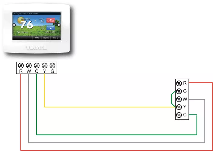
This is a common problem when replacing a mechanical thermostat or a thermostat powered by batteries. These older thermostats require 4 wires, but newer more sophisticated thermostats require a 5th wire known as the Common wire to power the digital display. There are three ways to add the common wire to a four wire installation:
Note: Before starting, we recommend that you take a picture of the original wiring to the old thermostat as reference to help remember what terminal each thermostat wire was connected to.
Option #1: The easiest and least expensive option is to sacrifice independent control of your indoor fan.
Caution: if your heating and cooling system is powered during the thermostat installation process and you accidentally touch the R (red) power wire to the C (blue or brown) common wire, then you will permanently damage either the equipment fuse or the transformer in the equipment.
Option #2: The second way to add a wire is to
install the ACC0410 Add-A-Wire accessory. Add-A-Wire allows two
thermostat signals to be controlled from one thermostat wire. As
above
move the green wire from the G terminal to the C terminal on the
thermostat and at your heating and cooling equipment. Now use the
Yellow wire to carry the Add-A-Wire signal. 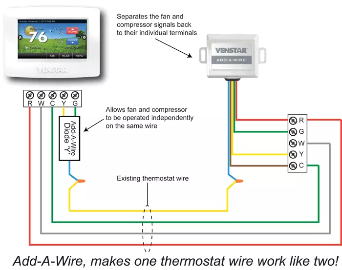
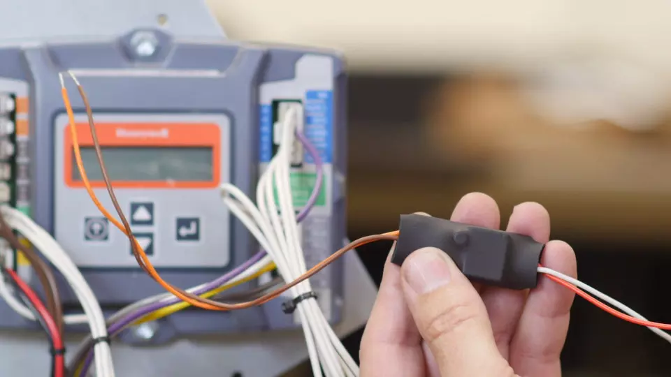
Add-A-Wire Diode and Add-A-Wire Box:
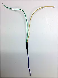

Add-A-Wire Model #ACC0410 In applications where additional wiring cannot be run, the Add-A-Wire accessory can be used to add a wire to the thermostat.
Option #3: The final way to add a wire is to contact a licesned HVAC contractor. This contractor will be able to run the necessary number of thermostat wires from your heating and cooling system to your thermostat. Please visit the Distributors section of our website to find the nearest HVAC wholesale distributor to your location. You may contact any of these distributors for an HVAC contractor referral in your area.
To control thermostats using an external timeclock, simply connect the two wires from the relay output on the timeclock to the two DRY CONTACT terminals on the thermostat. You should set the ‘dry contact use’ step for the function that you want to achieve. Depending on your model, the dry contact can force the thermostat to enter energy savings setpoints (like Vacation or Holiday) or to switch to comfort setpoints (Occupied).
Note: The thermostat requires a dry contact signal to control this function. That means that NO VOLTAGE can be presented by the external timeclock. If your device doesn’t provide a dry contact output or you are trying to slave multiple thermostats to the single device, you must use isolation relays for each thermostat. Contact support via the widget on this webpage to contact us for more information.
Venstar thermostats are sold only to authorized distributors in North America. Our distributors sell our products to their dealers and contractors. Most of these dealers/contractors sell & professionally install Venstar products. A few of these dealers sell Venstar products online through their own website or through an online retailer such as Amazon. Venstar itself does not sell thermostats direct to the consumer or online.
As the manufacturer of Venstar branded thermostats we offer training and support primarily to our distributors and their dealer/contractors.
Your place of purchase should be your first avenue of support. That being said, Venstar technicians will make every effort to answer your thermostat support questions by email. From this page you may access basic troubleshooting and helpful tips.